-1
Diagnostický případ
Opravené vozidlo


Intermittent Limp-in mode and same DTC's..
05.03.2011
| aktualizováno
14.03.2014 14:41:30
24534x
Informace o vozidle
| VIN: | TMBBS61Z752045709 |
| Výrobce: | Skoda |
| Model: | Octavia II |
| Rok výroby: | 2006 |
| Kód motoru: | 1.9 TDi |
| Typ motoru: | BKC |
| Výkon (kW): | 77 kW |
| Převodovka: | Manuální |
| Palivo: | Diesel |
| Najeto: | 0 km |
Jak se závada projevuje
Nouzový režim.
Jak často se závada projevuje
-
Sporadicky / za specifických podmínek.
- Za jiných podmínek. At any time
V jakém systému se závada vyskytuje
- Motoru.
- během jízdy
- [P0101 16485] Airmass sensor G70 - Implausible signal
- [P1557 16622] Boost pressure sensor G3 - Overboost
- trvalá závada
- sporadická závada
Doposud provedeno bez úspěchu
The boost pressure sensor was replaced 2x and the MAF sensor was replaced 1x. All previous attempts to repair the vehicle were unsucessful and the fault always reappears.According to the technicians the fault is very intermittent and cannot be reproduced.
Závěr
VOZIDLO JSEM NEOPRAVOVAL22.6.2009 23:32:18
Repaired. The cause was bad contact at a terminal panel under the air filter. (This terminal panel on modified el. harnesses has been cancelled). Due to contact resistance the boost pressure signal was distorted. The DTC relating to non-relevant intake air mass values can be explained that the manufacturer is most probably using not very accurate algorithms for generating DTC's.
15.6.2009 22:59:28
Not repaired yet. We are suspecting the ECU, but haven't measured the ECU. Before we start we will inspect the el. harness and all the terminals and connections.
Obrázky, fotografie a soubory
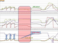
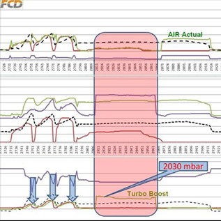
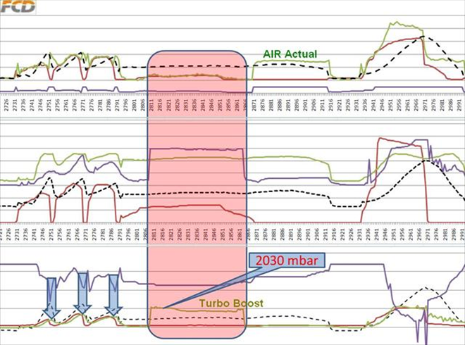
Log file from SuperVAG - fault recorded (4176/2)
The Limp-in mode is activated intermittently, but the actual fault occurred quite frequently. In the framed part of the recording we can see how the boost pressure signal (at the bottom) rises suddenly to a value of 2030 mbar without any load increase (all the lines are without any major change). We know that there is no such boost pressure in the system, when there is almost no load present. We can see that the system is incorrectly using this high boost pressure on the changing calculated fuel quantity for restricting torque, that jumps rapidly to its almost max. level (in the middle recording).
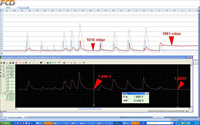
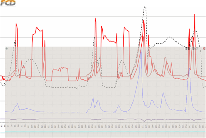
Oscilloscope compared to onboard diagnostics - test drive (4176/3)
Red = the boost pressure signal trace recorded by the onboard diagnosticsBlue trace copied to the Hyaline slide(greyblue frame on top of the recording) = Boost pressure sensor voltage on the connector.
While both traces should copy almost the same pattern and propotional size of changes, we can see on the recording that the red trace randomly jumps 3 times to higher values in positions where the blue trace at the bottom doesn't change its values. During the test drive the vehicle didn't switch to Limp-in mode, even though the fault on the recording shows quite frequently!!!
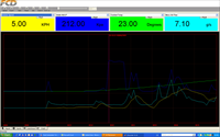
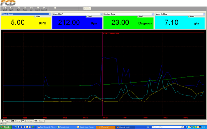
Initial diagnostics with C-Recorder (4176/4)
Yellow = vehicle speedBlue = turbocharger boost pressure
Green = coolant temperature
Light blue = Mass air flow
For intermittent faults we have good results with the C-Recorder. The C-Recorder data recording revealed that a fault was occuring more frequently than expected and compared to the occurences of the Limp-in mode. The recording also revealed where the fault would show.
During the engine warm-up phase almost every recording of individual test drives showed implausible boost pressure values in no engine load engine conditions. This happened even during test drives when the engine didn't go to a Limp-in mode. So the statement that the fault is very intermittent is not quite the case because the fault could be monitored by the diagnostic tools quite frequently. What was a very intermittent condition was the Limp-in mode.
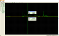
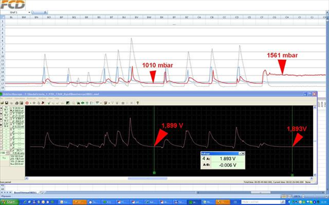
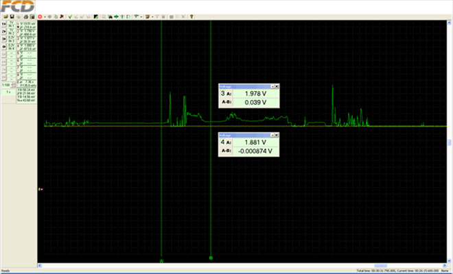
Difference between the transmitter and receiver (4176/7)
The top light recording is from onboard diagnostics, the bottom from an oscilloscope connected directly the boost pressure sensor connector. By making a simultaneous parallel measurement, we have discovered differences at the end of the recording (arrows).Red = information about the boost pressure signal pattern as given by the onboard diagnostics
White = voltage pattern on the turbocharger boost pressure sensor connector
Recording of repeated accelerations of a standing vehicle, when we tried to trigger the fault by warming the engine. After the last acceleration the boost pressure value on the top recording remains "hanging" on a value of about 1550 mbar. The fault can be anywhere between the boost pressure sensor and the processor on the ECU main board. Our original suspicion that the fault is in the ECU was excluded by performing further measurements on the boost pressure signal transmitter and receiver, including the power supply signals. This two pints measurement showed to the problem on the ECU connector and thus to the conclusion that the problem is in the el. wiring between the sensor and ECU.
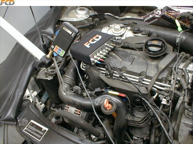
Recording and detecting the faulty contact on the terminal panel under the air filter (4176/8)
Yellow = boost pressure sensor voltage pattern on the sensor connector = OKGreen = boost pressure sensor voltage pattern on the ECU connector = changing signal = Not OK
DDuring this measuring process the fault occured at less frequent intervals, so we had to wait and we wiggled with the el. harness. We found another el. harness terminal panel under the air filter and when we touched this panel the signal changed. The fault is in this terminal panel.
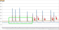
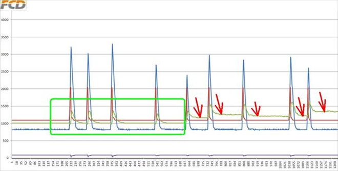
Recording and detecting the faulty contact on the terminal panel under the air filter (4176/9)
Repeated accelerations test on a standing vehicle in the workshop. The green frame shows a stage without a problem and the red arrows are pointing to a section where the fault started to show on its own. The boost pressure value suddenly stayed "floating" at higher values due to contact resistance in the terminal panel.

Two points measurement on the "transmitter" and on the "receiver" - Detecting the fault position (4176/12)
Thanks to the two points measuring system where a measurement is taken on the ECU and on the boost pressure sensor the fault position was traced to a defectice el. wiring harness. The faulty terminal connection was repaired by cleaning without the need to replace any components.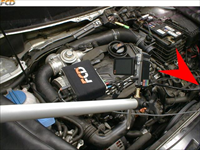
Detecting the fault position (4176/13)
When the purple wire in the terminal panel was touched it caused changes to the signal going to the ECU.
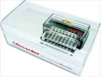
C-Recorder - little big helper with intermittent faults (4176/14)
C-Recorder is an affordable tool for analyzing intermittent faults. Not only workshops use this tool but also private owners purchase this tool to monitor their vehicles status or to find intermittent faults. This electronic tool in a clear plastic case can record up to 24 hours of driving data ( up to 33 starts and engine off conditions )and also records the freeze frame conditions when for a DTC. The instalation just requires that the tool is inserted into the OBD connector and the customer can drive up to 2 weeks. After that the C-Recorder is taken out and the recorded data is analyzed on a PC either using digital or graphic form. More info in the individual details....
Soubory ke stažení
-
exeTest drive Log - downloadable excel file (4176/5).exe Here is a complete test drive recording that you can download to your computer, so that you can make your own evaluation. The intermittent but very frequent changes of the boost pressure can be seen quite clearly.Stáhnout soubor
-
mwfAutoscope II recording for download (4176/6).mwf Here you can download this oscilloscope recording from a test drive to your PC that you can analyze. The recording shows no signs of a problem. Because the sensor is sending faultless signals to the ECU and because the ECU is receiving different information it is possible to assume that there is a problem in the el. harness between the ECU and the sensor or a fault in the actual ECU.Stáhnout soubor
-
exeBoost pressure sensor test recording - Excel file for download (4176/10).exe For easier identification the fault positions are marked by crosses and the good sections are marked by a tick symbol. At the end of the recording changes caused by wiggling the el. harness can be seen. The oscilloscope in these cases is inconquerable. After disconnecting and reconnecting the terminal panel connectors the fault didn't appear again.Stáhnout soubor
-
mwfFinding the fault - Autoscope II file for download (4176/11).mwf Green = boost pressure sensor signal input to the ECU measured on the engine ECU connector pinStáhnout soubor
Yellow = output boost pressure sensor signal on the sensor connector
When the el. harness was wiggled at the connector or if the actual connector was wigglewd the signals differed considerably.


Komentáře (0)