- 4 Aktuální žádosti o pomoc Poraďte svým kolegům
- Požádejte o pomoc
- Podejte dotaz do fóra
- Vložit hotový případ
- LOG Decoder

Žádost o pomoc
Žádost o pomoc vyplňte, pokud máte rozpracovaný diagnostický případ na konkrétním vozidle, u kterého potřebujete pomoci zjistit skutečnou příčinu závady.
Pro naše nekonvenční metody je nutný základ znalostí a mít vlastní vybavení minimálně pro "logování", lépe však osciloskop. Nejlepší přípravou pro práci jsou naše videoškolení a akademie.
Jak to funguje?
Do online formuláře v jednotlivých krocích vyplníte všechny důležité údaje k případu a poté Vám ostatní registrovaní diagnostici poradí v komentářích*.
Supervizor a moderátoři FCD.eu samozřejmě vše doplňují a kontrolují správnost informací, aby cesta vedla ke správnému cíli.
Požádat o pomocDiagnostický případ


Exotic TATRA 613-4 injection
Informace o vozidle
| VIN: | TMT613016SP011748+ |
| Výrobce: | Tatra |
| Model: | 613-4 Injection |
| Rok výroby: | 1995 |
| Kód motoru: | V8 i |
| Typ motoru: | 613-4 i |
| Výkon (kW): | 147 kW |
| Převodovka: | Manuální |
| Palivo: | Benzín |
| Najeto: | 145 194 km |
Jak se závada projevuje
Nefunguje / funguje nesprávně. Engine stalling (including while driving) and followed by a period of time when it's impossible to start the engine.
Jak často se závada projevuje
- Trvale přítomná závada.
V jakém systému se závada vyskytuje
- Motoru.
- neukládá žádný chybový kód
Doposud provedeno bez úspěchu
Various attempts with control unit replacement to see if it's defective. Then the other assumption was that the engine speed sensor could be defective. Sensor replacement requires engine removal because the sensor isn't accessible. The other suspected causes were the Lambda sensors, or that the catalytic layer of the converter was no longer working...Závěr
VOZIDLO JSEM OPRAVILWe only accepted the car into the FCD Garage because of a lot of pressure from Tatra fans to do a multi-issue analysis, which we did. The fault that caused the engine to intermittently stall unexpectedly was in the ignition coil primary power supply circuit (terminal no. 15). Our next task was to investigate how the system works in the "fragile" starting phase, either hot or cold, which was also successful, and why the system does not operate in stoichiometric mode in the Lambda sensor control loop. This was successful and we discovered that the engine couldn't reduce the fuel quantity anymore (–10 % maximum adaptive).
Many useful facts have been revealed (mainly what should have been revealed), but according to some of the findings, we have the impression that this car model is in an "unfinished" development stage. We tested the Lambda open/closed control loops with the assistance of Jirka Zima, who connected to the engine control unit and found that the temperatures on three sensors (intake air, cylinder head, engine oil) had reached the limit of the Closed Loop condition (Lambda sensor control loop for controlling the mixture in the Lambda window).
Overall, there are too many weaknesses. For example, ignition and injection. The ignition coil is weak, and the sparks are suppressed by the compressed air at start-up. The spark plugs are literally flooded by the simultaneous injection, because by the time the last firing cylinder reaches the combustion phase, it receives a total of 8 fuel injections, while the previous ones have always one less. It was probably well intended to give the engine enough fuel as soon as possible, but the way it actually works, it does, strangely enough, everything to flood the engine when cold. The engineers probably didn't intend to create that, but they inadvertently did, and that's why it often becomes flooded.
Simultaneous injection in an engine with more than 4 cylinders is simply pointless, just because of the 8 injections of the last firing cylinder. The last spark plug flooding is a problem even on a six-cylinder engine. Another weakness is the cold idle speed control, which is set too low and the idle valve itself fails to maintain an accurate engine speed in the comfortable range. Those fluctuations and the erratic engine speed aren't a pleasure to listen to. This is because there is no so-called fast idle control by changing the ignition advance, which is common in today's engines. However, the engine management on this engine is quite primitive and does not interact with the bypass valve to regulate idle speed. Bypass valve intervention is too slow to smooth out the idle speed fluctuations.
To sum up the engine management on this air-cooled 8-cylinder engine its behaviour is very crude and unacceptable by today's standards. Similar behaviour is common on modified racing engines, where idling is the last thing that the racing driver with helmets is worried about.
Not only to criticise, some things can be improved despite all the limitations. For example, by installing a boosted ignition set, for example, the MDS system can during a single expansion stroke generate up to 5 powerful sparks in a row, so instead of a half-second-long electric spark, it is possible to achieve 10 to 15-millisecond-long series of high-voltage sparks. This would improve the comfort of the first restart after a prolonged shutdown period.
Now all that remains is that "somebody" will measure the system fuel pressure. We didn't because the hoses are hard as a rock, the quick couplers are covered in a layer of rubberised mastic, everything is old and blistered, and all the hoses require revision/replacement) and verify that the fuel pressure is not higher than about 3 bar (I hope that I remembered this value correctly). However, if the fuel pressure matches the specified pressure according to the shop manual, then the problem could be that the engine has injectors with larger holes that inject more fuel for the same opening time at the same fuel pressure.
Obrázky, fotografie a soubory
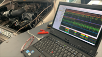
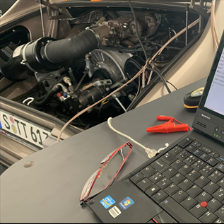
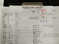
Tatra 613 with GEMS engine management system (16258/1)
First cold start and a test measurement to make sure I was connected everywhere correctly, and immediately the engine stalled. Before I could change the voltage ranges, the engine had stalled, and I could see the first fault on the power supply to the ignition coil.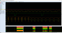
First recording and the engine stalled (16258/2)
Although I had accidentally set all channels to only 6 Volts, you can still see how the power to the ignition coil (yellow = terminal vol 15) failed, but the voltage at the injectors (green), which comes from the same junction, hasn't dropped to the same low voltage value. The fault is somewhere between the last common point and the coil...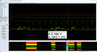
Attempt to start the engine, but it doesn't start (16258/3)
On subsequent attempts to start, you can see how the power supply fails due to an " insufficient contact".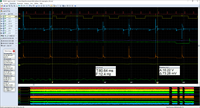
When everything is working as it should (16258/4)
Another start the next morning was successful without a problem. Only the rpm fluctuated to 470 rpm after a cold start and then settled down to 740 rpm - oddly enough, rising to 1040 rpm after a while and staying there through the warm-up phase.The speed and position sensors (crank and cam) were free of defects, so their suspected "disappearance" hasn't been confirmed. Likewise, the other signals are like they should be.
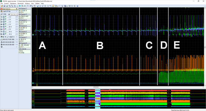
Unsuccessful cold start attempt (without touching the accelerator pedal) (16258/5)
Cold starts are a lottery for the Tatra due to the following reasons:A) The air bypass valve is more open and more air (higher compression pressure) suppresses the spark, so the burn time is 4 times shorter than the minimum arc burn time.
B) The injectors inject all together at TDC of all cylinders (8 x per 720°crank revolution) and if the mixture isn't ignited, the spark plug remains wet. The wet/moist spark plug generates cold spark tracking across the spark plug material (the spark doesn't burn between the electrodes but creeps across the material = not good)
C) Flooded spark plugs forming cold arc tracking don't give the engine a chance to start = they don't ignite the mixture and become wetter = a much higher possibility of spark tracking faults
D) The idle valve, even at its widest opening, doesn't provide enough air to clear the wet plugs
E) The accelerator pedal must be depressed to dry-out the spark plugs
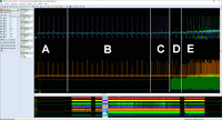
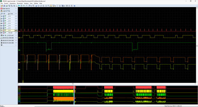
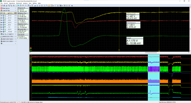
Problematic system generated behaviour (16258/6)
This record does not show a fault (defect), but problematic system behaviour that causes the engine to perform as badly as it does:A) Simultaneous operation of all injectors at the same time. At this point, the accelerator pedal isn't depressed, and the engine can't start with the flooded spark plugs.
B) The accelerator pedal was applied at this point. The control unit starts intentionally limiting the injected fuel quantity (probably an emergency rescue mode based on the "load" signal at start-up with an obvious intention to apply a spark plug "dry-out" mode at the last moment at any cost).
C) The controller's intention to "restrict the fuel" is successful, the first spark plugs dry out, and the "cold spark tracking" slowly disappears, the first sparks finally ignite the arcs between the electrodes, and the engine begins to run on its own combustion power.
D) A very clumsy and awkward transition mode, where the unit switches from "simultaneous" to "sequential" injection mode and the engine slows down again in this "awkward pause". At the same time, the air bypass valve above the throttle body starts cycling and the engine is switched to "idle" from that point on.
E) The engine starts running with "combustion" power, but with numerous cylinder misfires, their spark plugs still haven't dried out, and they have cold spark tracking with a very short arc burn time across the electrode surface (not between the ends of the electrodes). About 5 to 6 cylinders are working, the others will slowly join within 10 to 20 seconds...

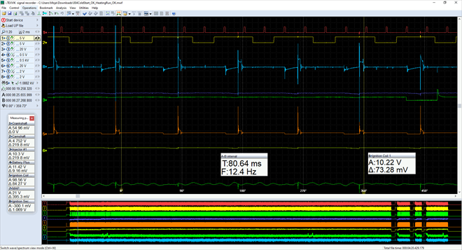
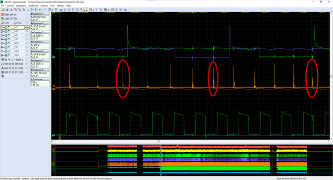
The engine starts running immediately after a flooded start (16258/7)
A few seconds after a flooded start, the engine runs erratically. This is caused by cold spark tracking of the wet plugs (highlighted in red).Explanation. An engineer's flaw. Engineers who don't have engine grime under their fingernails are denied the ability to see the consequences of their decisions. Simultaneous injection carries well-known risks at engine start-up. At starting rpm, the engine must start with one firing cylinder. Even if, in theory, the first cylinder fires correctly, the others are still waiting for their first firing according to their firing order.
The first cylinder that could ignite doesn't usually have enough fuel from a single injection. The result is that the engine fires up on the second or even the third firing cylinder. The engine does start up, but simultaneous injection (injection at each TDC of each cylinder) causes the 3rd cylinder to receive four injections, before firing up. The 4th cylinder received five injections, the 5th cylinder received six injections, the 6th cylinder then seven injections, and the 7th cylinder eight injections. The first cylinder that didn't ignite initially received a total of nine injections of fuel into the intake at this point so before the next firing order the spark plug is completely flooded and doesn't have the ability to ignite the mixture.
As a result of the different injected fuel quantities at the first turn of the starter, the engine suffers from fouled/flooded spark plugs. The flooded spark plugs are those that come after the first successful cylinder that (accidentally) fires up, because each successive cylinder always has 100% more fuel, then 200%, 300%, 400%, etc. up to 800% more fuel than it requires.
Another pitfall of this simultaneous injection solution during starting is that if it doesn't fire up the engine on the first try, then in principle, it can't start the engine afterwards. This is because the idle bypass valve (another design blunder on a large displacement V8) can't provide the engine with as much air as would be required to vent/dry out the 1000% to 2000% richer mixture that has flooded all the spark plugs.
Simultaneous injection may be tolerable for a four-cylinder engine. Still, for a six-cylinder and even worse for an eight-cylinder, the engineer should consider whether the fuel can be dosed equally to all cylinders during the starting phase or a similar quantity. After all, there are more options, but with multipoint injection to apply simultaneous injection is a designer's novice mistake.
Within around 10 seconds after the start, all cylinders are finally running (16258/8)
As soon as the engine is running, the individual spark plugs dry out due to the sequential injection rhythm (only one injection, always before the opening of the intake valve), and the cylinders are all working at this point.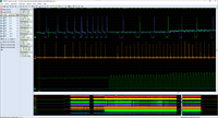
This is how the "switchover" looks like in GEMS (16258/9)
The standard behaviour of the engine when switching from simultaneous to sequential mode is associated with a "pause" where the engine neither injects nor ignites for two cycles. Then it operates from other maps used for normal "engine operation".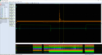
The ignition coil power is at the limit (16258/10)
This is a picture of one of the sparks at standard semi-warm idle. The spark burn time is at the limit (only 600 microseconds), and that's still with a fairly rich mixture! The coil doesn't give the longer burn time a chance to burn longer with the current spark plug electrode gap. Burning an electric arc from half a millisecond does not heat the mixture to ignition temperature and risks misfiring. However, these are not typical "misfires", but so-called "late flame front ignitions", which can be traced to the behaviour of Lambda sensors. The mixture will ignite, but since the temperature centre around the spark is too small, the fuel will be slow to ignite, and the highest force on the piston will come late. It's as if a late ignition advance was set on the cylinder in question. Such ignition of the mixture can raise the temperature in the exhaust manifolds.
Lambda sensor behaviour (16258/11)
The Lambda sensors in front of the three-way catalyst don't allow the catalyst to convert unless the three temperature sensor temperature values are not above +50 °C.Documentation citation: "Oxygen Sensors
NTK Thick Film Heated Titanium sensors placed in the exhaust stream (one per bank before catalysts) provide a voltage value typically between 0 – 1 volt with the ECU providing a gain of times three. The voltage switching characteristics of this sensor at stoichiometric air/fuel ratio thus indicate a lean condition for voltages up to the switch point of 1.5 volts ( .500 mV at the sensor) and a rich condition if higher.
END OF CITATION
At these temperatures, the feedback fuel control is not activated.
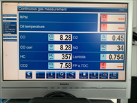
Exhaust emissions left exhaust (16258/12)
Pod + 50 °C na třech snímačích je zde "Open Loop", směs je velmi bohatá.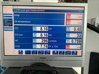
Exhaust emissions right exhaust (16258/13)
The system is in "Open Loop" mode when the three sensors are showing a temperature below +50 °C, and therefore the mixture is very rich.
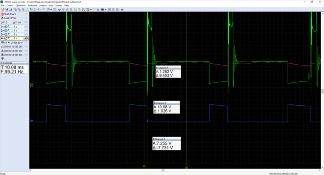
Monitoring the ignition module (16258/14)
Three terminals on the ignition module (1 = terminal 1 on the coil; 2 = +12 V power supply; 3 = signal from the engine ECU with a value around 7.3 V). Here you can see that the power supply has only 11 V and not 13.5 V which is the onboard voltage value. I can't replicate the ignition coil power failure (a drop to 2 V). The first time it failed a week ago, the 12 V power supply dropped out (on channel 2), not quite to zero, but to some voltage over about 2 V!Reviewing the wiring from the battery to the ignition coil supply should reveal a voltage drop of around 2 V.
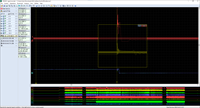
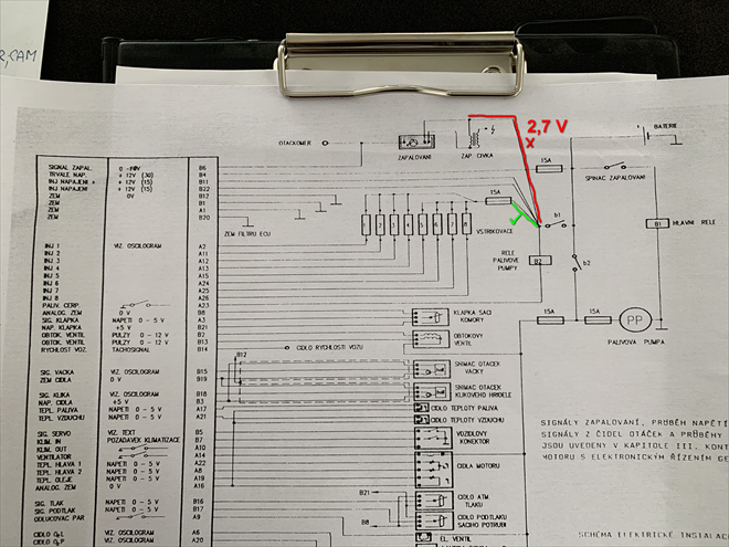
Fault isolation (16258/15)
The fault will be located somewhere in the red area, but I don't know exactly where. I'm missing that point. The point at which it drops to about 2.5 volts and why. Because the common junction supplies power to the injectors, they stayed energised during the one failure I was lucky enough to record. As to whether the ignition module could be doing this, it is a mystery due to the incomplete schematic diagram.
The fault was revealed by restricting the power of the fuel pump (16258/16)
Simulations can be used to determine the type of fault. The computer wizard Jirka Zima managed to communicate with the control unit and found that all conditions were met for the Lambda sensor closed-loop control. The electrical readings of the lambda sensors showed high voltage values. This is an indication that the control unit must lean out the mixture.After the conditions were met, we looked at what the control unit was doing and at that point, it was trying to reduce the injection times but reached its limit (almost –10%) and couldn't go any further.
So we tried to get to a lower injection quantity another way: By reducing the fuel pump's power. By reducing the power to the pump from the original 4 amps to 2.8 amps, we reduced the injected fuel quantity so that the control unit managed to achieve the stoichiometric ratio.
Both Lambda sensors started working at that point, and the catalytic converter eliminated all poisonous emissions to near zero.

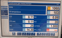
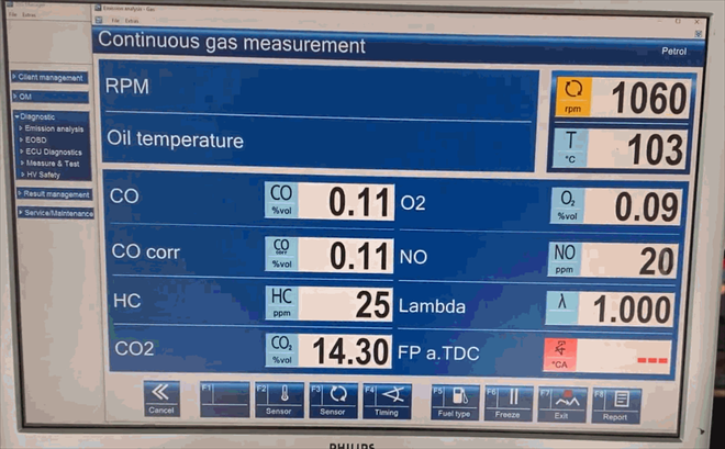
The Tatra is operating at almost zero poisonous emissions at Lambda = 11 (16258/17)
The exhaust gas analyzer is reading 0.05 % CO, 25 ppm NO and HC and Lambda is at 1.003!These results clearly confirm that the engine has an issue with the fuel quantity control. Either the fuel injection pressure is too high or the fuel injectors are larger than the specification.
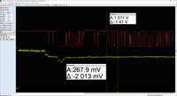
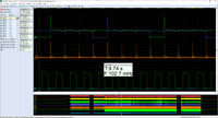
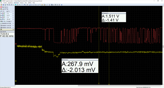
Fuel pressure recording at Lambda sensor closed-loop (16258/18)
Yellow = current to fuel pumpRed = signal of Titanium lambda sensor
As soon as we reduced the pump current to almost half via the PWM signal, both Lambda probes started to work so that the control unit could adjust the mixture to the stoichiometric ratio.


Komentáře (0)